This project is still a bit of a work in progress but the heavy lifting is done. Now that we’re getting to an appropriate age for power wheels, I had the idea to recreate one of the vehicles from my senior thesis in College- affectionately named the “juggernaut”. This was a fun thing thing to build back then, and its been even more fun to build at this scale. The original concept was basically “laser tag” for R/C vehicles- with some fun tech thrown in. The Juggernaut in particular featured a mechanically linked 6 wheel drive- the front and rear wheels were wired to pivot opposite directions, and the chassis articulated at least 45 degrees at the center axle. This allowed it to climb stairs and substantial other articles on the fly while still maintaining steering control. For the laser tag portion- it had a turret that could pivot 360 degrees and fire it’s infrared cannon while relating a continuous FPV perspective through a CCD camera. All of which was pretty state of the art at the time but it’s commonplace now.
Anyway- that’s just a walk down memory lane for me- but this version maintains the key features of 6 wheel drive (but not mechanically linked), essentially the same steering setup (although mechanical- not electrical), and the same articulating chassis which pivots at the center axle. As it turns out, a military vehicle exited which utilized a similar design. Check out the “gamma goat” for an interesting read. (Further, even wilder coincidence: The WW2 era factory for it still stands & has been converted to a massive social hub here in Charlotte, and features a vintage gamma goat displayed inside a giant glass enclosure... whaaat?)
Ok- onto the build:
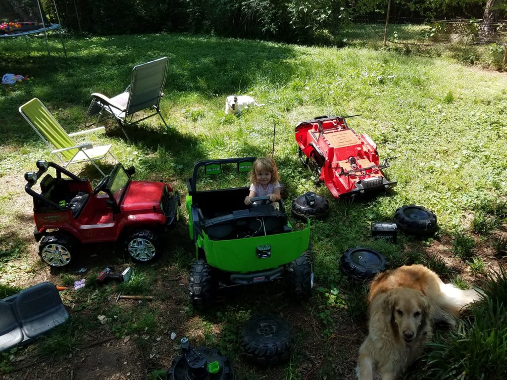
This challenge took a few months of patience- but honestly was kicked off after noticing a neighbor’s red jeep awaiting trash pickup.. I wanted to save a few powerwheels from the landfill so I started paying attention to cheap/broken/free powerwheels opportunities after that. Before too long, I had collected 3 examples of assorted powerwheels. One John Deer tractor, that jeep, and another. One had a very worn/problematic gearbox set but easily fixed with a new set of cluster gears available on Amazon. All examples have nice cascading pitch gearboxes. In a perfect world I would have found the same model and ratio gearboxes for this project- but I was pretty pleased at the reasonably similar performance of these after some further testing. Of course they’re not identical, but not bad. My thought was to try and manage all of these by wiring all 6 gearboxes in parallel to a single ESC. I was actually surprised to find that this works better than I expected. My plan B was (maybe still is depending on how much interest she has) to use a separate ESC for each pair of gearmotors and then dial them in to match torque/rpm. Not quite sure how I’d control them all simultaneously, but for now it looks like it works passably in the primitive config I’m using now.
The trickiest part to this whole plan really was adding gearboxes to the cheap ackerman setups that these powerwheels come with. I had to get a little creative and I had to come up with a separate approach for each different design. The John Deere was an easier transition- had to weld up a very custom setup for the jeep, but it seems to work.
So basically- the Jeep is left generally intact with the back chopped off, and modular gearboxes added to the front wheels and allowed to pivot with the wheels. The rear is now the John Deere front end with a similar gearbox modification. The front (formerly the back) of the JD is now chopped off with fabricated struts that attach to what’s left of the frame to the center axle (rear axle of the jeep). Just because that donor vehicle had a little plastic utility bed attached, I sliced off any protruding frame components and bolted that bed to what was formerly the front end of the JD. This is especially cool because it has a fold down tailgate- so when that gate is installed it returns to its original function. When it’s removed, it ends up being a nice bench seat for kids in the back. At this writing some safety solution needs to happen re: the articulating chassis because it essentially creates a kid-chopper between the front and back attached frames. It may end up being an accordion style bellows shield. I was also thinking about adding a watergun turret for authenticity points. We’ll see.
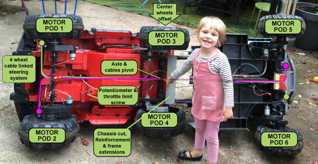
Finally, the steering in nearly all of these is as cheap as possible, and what that means is a very short throw where an offset bend from the steering wheel axle pushes on a slot in the steering crossbar. This makes for fast wheels turns and requires relatively high torque to operate even normally. It would require more than twice the torque to pivot 4 wheels simultaneously.
I reconfigured this using a 3/8″ diameter fiberglass rod and tether system. Now we have lots of torque (too much, really- it can self-destruct pretty easily) generated over about 1-2 full rotations. I should probably put a closeup photo of this system for clarity..
The paintjob on this is a tribute to the original “Juggernaut” vehicle, but has an overlaid glitter paint- a nice touch, but it takes a ton of “paint’ to get any coverage, so if we tried to color match it and then just do a light coat over everything.
The ESC for all this is a surprisingly cheap and appropriate one I picked up off Amazon. Really quite ideal- it claims 60A continuous current and 10-55v. That’s pretty impressive for a $28 ESC. After testing current draw, we should be less than 60A continuous draw, although I would be surprised if it wasn’t overrated spec-wise. I may add some fans & thermal compound for insurance. The best part about this component is that instead of the conventional on/off that powerwheels provide- this will provide a proportional control to both forward and reverse. Perfect! It even has a DPDT switch control for that function that can be wired as a drop in to the stock powerwheels control. It was a little tricky getting a proportional system in place of the former momentary switch formerly occupying that space. I ended up adding a linear potentiometer and then running a thin cord into the “engine” compartment- it connects to a typical extension spring. Seems to work great- full range of travel. Presently I have a throttle limit screw installed behind the pedal- seems PLENTY fast as is and I’d guess it’s only operating at 50% throttle at best. I’m actually quite surprised that it’s working as well as it is driving 6 motors (3 different specs!) simultaneously. That was a hail mary!
Battery: For now, I picked up a “dead” 40v LiPo pack as a freebie from a local dealer. Opening it up revealed a 20 cell pack with only two bad cells. I rewired said pack as below to be a 11.1v high output 18 cell pack- just bypassing the dead cells and leaving them in place.

So that’s about it for now. Here’s some regrets/observations:
The pivot points on the front/rear steering are different. Therefore in order to mechanically link them to match, I had to drill some new connection points and make a custom mount part. I wish I had noticed/measured this earlier.
Also, I don’t know why I didn’t realize it while building it, but the John Deere chassis wheelbase is longer than the jeep- so while I kept it the same, it would drive better if I shortened it to match. The upside of this, is that the “trailer” has some enough extra foot space to pull another rider or two- if (I can handle that whole kid chopping situation).
The rear wheels on this necessarily stick out further than the front. This isn’t ideal but neither is the fact that all sets of wheels would turn at different rates if not equalized by ground contact. If I come across some better wheel choices and want to keep improving things, this is a good area of focus.
I’ve kept a few cosmetic parts along the way- Lights, bumpers, etc. I’m mostly concerned with function but not opposed to blinging things up a bit once I get the rest sorted out.
Not much 3d Printing was involved in this, but I did manage to come up with a really handy spring loaded potentiometer assembly. You’ll need some type of input to determine what speed (if any) to move. That’s what the pot is used for. You can download the files and instructions for that assembly here.
.